Analog vs Digital Signal — Full Comparison & Selection Guide | ICMASS
Analog vs Digital Signal - Full Comparison & Selection Guide | ICMASS
Every circuit designer hits this decision. You have a sensor, a control loop, or a communication link - do you keep it analog, or convert to digital? The answer isn't "digital is always better." It depends on what you're measuring, how far the signal travels, and what's already on the other end.
Analog signals are continuous - they vary smoothly and can take any value within a range. A 4–20 mA current loop in a factory, a microphone output, the voltage across a thermistor. Digital signals are discrete - they represent values as binary numbers (0s and 1s) and switch between defined voltage levels. An I²C sensor output, a PWM control line, an Ethernet frame.
The core trade-off: analog gives you infinite resolution but degrades with distance and noise. Digital gives you noise immunity and perfect copies - at the cost of quantization error and conversion latency. This guide lays out the parameters, the decision framework, and the edge cases where the "obvious" choice is wrong.
Analog vs Digital: Side-by-Side Comparison
| Parameter | Analog Signal | Digital Signal |
|---|---|---|
| Nature | Continuous - infinite values within range | Discrete - finite values, typically binary (0/1) |
| Waveform | Smooth, continuous (sine-like) | Step-wise, switching (square wave) |
| Resolution | Theoretically infinite, limited by noise floor | Limited by bit depth (quantization steps) |
| Noise Immunity | Low - noise adds directly to signal | High - noise below threshold ignored; error correction possible |
| Signal Degradation | Degrades with distance, copies, and time | Regenerable - repeaters restore perfect signal |
| Bandwidth | Lower for same information content | Higher - more bits = more bandwidth |
| Power (simple circuits) | Lower - passive components often sufficient | Higher - needs active conversion and processing |
| Error Detection | No built-in mechanism | Parity, CRC, Hamming codes, checksums |
| Security / Encryption | Difficult - cannot be encrypted directly | Easy - AES, RSA, TLS layers |
| Storage | Difficult - requires continuous media (tape, film) | Easy - binary storage (RAM, flash, SSD); lossless copies |
| Distance | Limited - attenuation and noise accumulate | Unlimited with repeaters - signal regenerated at each hop |
| Latency | Zero conversion delay - real-time | ADC/DAC conversion + processing adds measurable delay |
| Flexibility | Fixed hardware - redesign to change function | Reprogrammable - software changes behavior |
| Component Types | Op-amps, resistors, capacitors, inductors, transistors | Logic gates, MCUs, FPGAs, ADCs, DACs, flip-flops |
| Real-World Interface | Direct - no conversion needed | Requires ADC (input) and DAC (output) |
| Multi-Parameter Transmission | One signal per wire (or frequency-multiplexed) | Many parameters over single bus (I²C, SPI, CAN, Ethernet) |
| Cost (simple task) | Lower - fewer components | Higher - overkill for basic functions |
| Cost (complex task) | High - precision analog ICs are expensive | Low - mass-produced digital ICs, economies of scale |
| Typical Voltage Levels | Any value within range (0–10V, 4–20mA, ±15V) | Defined logic levels (0–0.8V LOW, 2.0–5V HIGH for TTL) |
Key Differences
1. Physical Representation: How the Signal Carries Information
An analog signal mirrors the physical quantity it represents. A thermocouple produces a voltage proportional to temperature. A microphone outputs a voltage proportional to sound pressure. The relationship is direct and linear - the signal is an analog (a physical analogy) of the measured quantity.
A digital signal encodes information as numbers. The relationship between the bits and the physical world is arbitrary - defined by a protocol, a data format, or a calibration table. A 12-bit ADC reading of 2047 means nothing without knowing the reference voltage and the sensor's transfer function. The encoding is the strength (you can add metadata, timestamps, error correction) and the weakness (you need decoding logic at both ends).
2. Noise: The Deciding Factor in Most Real-World Decisions
In an analog system, noise adds directly to the signal. A 10 mV ripple on a 5V analog sensor output degrades accuracy by 0.2% - and once it's there, you can't remove it without also removing some of the signal. Filtering helps but can't fully separate signal from noise when they occupy the same frequency band.
In a digital system, noise below the logic threshold is simply ignored. A 1.2V spike on a 5V CMOS line? Still a logic LOW (threshold ~2.5V). No effect on the data. This is why digital dominates in electrically noisy environments - factories with VFDs, automotive engine compartments, anywhere with switching power converters nearby.
The trade-off: digital's noise immunity comes from the ADC step. If the analog front-end before the ADC is noisy, those errors are digitized along with the signal and become permanent. Garbage in, garbage out - digital doesn't fix a bad analog front-end.
3. Distance: When the Cable Length Decides for You
Analog signals attenuate. A 0–10V sensor output run 100 meters picks up voltage drop in the cable (I×R losses) and capacitively coupled noise from nearby power lines. By the time it reaches the controller, the signal-to-noise ratio may be unusable. The 4–20 mA current loop standard was invented specifically to solve this - current doesn't drop over distance the way voltage does, and the 4 mA live-zero detects broken wires.
Digital signals can be regenerated. RS-485 (differential digital) runs reliably over 1,200 meters. Fiber optic digital links span kilometers. Each repeater or switch along the path reconstructs a perfect copy of the original bits - distance becomes a latency issue, not a fidelity issue.
4. The Conversion Penalty: What You Lose Going A→D→A
Every ADC introduces two errors: quantization error (rounding the continuous value to the nearest digital step) and sampling error (missing what happens between samples). A 10-bit ADC on a 0–5V range has 4.9 mV per step - any voltage between steps is rounded. Increasing resolution to 16-bit shrinks the step to 76 µV but doesn't eliminate it. And sampling at 1 kHz means a 600 Hz transient between samples is invisible.
For most applications, 12–16 bits at an appropriate sample rate is more than adequate. But for precision analog applications - strain gauge bridges, precision current sensing, medical ECG - the ADC's noise floor and linearity become the limiting factors. In those cases, staying analog through the front-end amplification stage, before digitizing, preserves signal integrity that early digitization would lose.
When to Choose Analog
| Scenario | Why Analog Wins |
|---|---|
| Simple single-parameter sensing - one thermistor, one pressure transducer, one light level | No ADC, no MCU, no firmware. A resistor divider into a comparator gives you a threshold switch. Analog is cheaper, simpler, and more reliable for single-point measurement. |
| High-fidelity audio front-ends - microphone preamps, phono stages, instrument inputs | Every dB of noise added before the ADC is permanent. High-quality analog front-ends preserve dynamic range that even 24-bit ADCs can't recover if lost early. The analog stage sets the noise floor for the entire chain. |
| 4–20 mA industrial loops - process control in factories, refineries, chemical plants | Current loops are immune to voltage drop over distance, inherently detect broken wires (current < 4 mA = fault), and don't need firmware updates. A 40-year-old 4–20 mA transmitter still works with a brand-new PLC. |
| Real-time control with zero latency tolerance - analog PLLs, servo motor current loops, class-D amplifier feedback | Digital control loops have ADC conversion time + processing time + DAC settling time. An analog op-amp control loop has none of that - the feedback is continuous and instantaneous. For current-mode control in SMPS at 500 kHz, analog still beats digital on speed. |
| Battery-powered always-on sensing - wake-on-sound, motion detection, threshold monitoring | A comparator + a few passive components draws nanoamps. A microcontroller with an ADC, even in sleep mode, draws microamps. For a device that must run 5 years on a coin cell, analog front-end wake-up circuits are irreplaceable. |
When to Choose Digital
| Scenario | Why Digital Wins |
|---|---|
| Electrically noisy environments - next to VFDs, switching converters, motor drives, automotive | Digital thresholds reject noise below the logic transition level. Add differential signaling (RS-485, CAN, LVDS) and you get common-mode noise rejection on top of threshold immunity. Analog signals in the same environment need shielded twisted-pair cable, ferrite beads, and careful grounding - and they still pick up noise. |
| Multi-parameter monitoring - smart sensors, IoT nodes, medical devices measuring 6+ channels | One I²C or SPI bus carries temperature, humidity, pressure, acceleration, and device status - on 4 wires. Doing the same with analog would need one wire pair per parameter plus calibration for each. Digital scales; analog multiplies wiring. |
| Long-distance transmission - building automation, remote monitoring, distributed data acquisition | RS-485 runs 1,200 m. Ethernet runs 100 m per segment, unlimited with switches. Fiber runs kilometers. Each hop regenerates a perfect copy. Analog over the same distance needs signal conditioning at every stage. |
| Data that needs storage, encryption, or compression - medical records, financial transactions, surveillance | You cannot encrypt an analog signal in any meaningful way. Digital data supports AES-256, TLS, digital signatures. For any application where data integrity and confidentiality matter, digital is the only option. |
| Systems that evolve over time - products with firmware updates, field-upgradable devices, research instruments | Digital logic is software-defined. Add a filter? Change a line of code. Support a new sensor? Update the firmware. Analog circuits are etched in copper - to change behavior, you change the PCB. For any product that might need feature updates after deployment, digital pays for itself on the first firmware release. |
| High-precision measurement beyond ~14 bits of SNR - precision scales, spectroscopy, metrology | Below 10–14 bits of effective SNR, analog can be cheaper. Above that, precision analog components (0.01% resistors, low-drift op-amps, precision voltage references) become expensive fast. A 24-bit delta-sigma ADC with a $2 microcontroller outperforms a pure-analog equivalent that costs 10× as much. |
Frequently Asked Questions About Analog vs Digital Signals
Q1: Is every signal actually analog at the physical level?
A: Yes - and this confuses a lot of people. Even a "digital" square wave switching from 0V to 5V passes through every intermediate voltage during the transition. The distinction is about how we interpret the signal. Digital means we only care about the value at specific sampling instants and ignore what happens between them. The voltage during the transition edge is considered meaningless. In analog, every point on the waveform carries information.
Q2: Can I convert an analog signal to digital without losing information?
A: No - you always lose something. Quantization rounds continuous values to the nearest digital step. Sampling misses what happens between sample points. But the practical question is whether the loss matters. A 16-bit ADC on a 0–5V range has 76 µV steps - for most sensor applications, the sensor's own noise is larger than the ADC step. And sampling at 10× the signal bandwidth (Nyquist with margin) captures all practically relevant information. The information loss is real but usually negligible.
Q3: Why are 4–20 mA current loops still used instead of digital buses?
A: Three reasons. First, current doesn't attenuate over distance - a 4–20 mA loop at 1,000 meters reads the same current at both ends. Second, the 4 mA live-zero detects faults: if the current drops below 4 mA, the wire is broken or the transmitter failed. A digital bus needs separate diagnostics for that. Third, installed base - refineries and chemical plants have millions of 4–20 mA loops. Replacing them with digital means rewiring, revalidating, and recertifying safety systems. The cost and downtime aren't justified when the existing loops work fine.
Q4: Does digital always mean better accuracy?
A: Not automatically. Digital accuracy is only as good as the analog front-end before the ADC. If your signal conditioning amplifies noise, adds offset, or drifts with temperature, digitizing those errors doesn't remove them - it makes them permanent. A well-designed analog signal chain can outperform a poorly-designed digital one. "Digital" is not a substitute for good analog engineering - it's a downstream benefit that depends on upstream analog quality.
Q5: When should I stay analog instead of adding a microcontroller?
A: Three clear cases. (1) The function is dead simple - a threshold switch, a gain stage, a filter. Adding an MCU, ADC, firmware, and a programming header to replace one op-amp is overengineering. (2) Power budget is extreme - an analog comparator draws nanoamps; any MCU in active mode draws at least microamps. (3) Latency must be zero - analog feedback loops (PLLs, current-mode SMPS control) operate in nanoseconds. A digital loop adds ADC + processing + DAC delay that may be unacceptable at the switching frequency.
Q6: What's the cheapest way to send an analog signal over a long distance?
A: Convert to 4–20 mA at the source. A simple two-wire transmitter IC (like the XTR116) modulates the supply current based on the sensor input. At the receiving end, a precision resistor (typically 250Ω) converts 4–20 mA to 1–5V for your ADC or analog input. Total BOM cost is a few dollars, and the loop runs hundreds of meters on twisted pair. If you need digital at the far end, RS-485 with Modbus RTU is the next step up - similar wiring, but you get multiple parameters, error checking, and device addressing.
Q7: Are "continuous = analog" and "discrete = digital" correct definitions?
A: Not exactly - this is a common misconception discussed on DSP StackExchange. Signals have two independent axes: time (X) and amplitude (Y). A sample-and-hold output is discrete in time (sampled) but continuous in amplitude - it's a discrete-analog signal. A true "digital" signal is discrete in both time and amplitude. The terms get used loosely in practice, but understanding the distinction matters when you're debugging why a sampled signal doesn't match the original.
Q8: How do I choose between analog and digital for a new design?
A: Run through these five questions in order. (1) Is the environment electrically noisy? → Digital. (2) Is the distance more than 10 meters? → Digital or 4–20 mA. (3) Do you need to store, encrypt, or transmit the data over a network? → Digital. (4) Is the function a single, simple measurement with no configuration needed? → Analog may be simpler and cheaper. (5) Will the product need firmware updates or feature changes after deployment? → Digital. If you answered "no" to all five, analog is likely the right call. If you answered "yes" to any of the first three, digital is the safer bet.
Related information



-
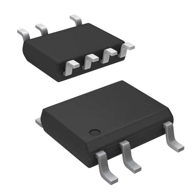
LNK304DN-TL Power Integrations
-
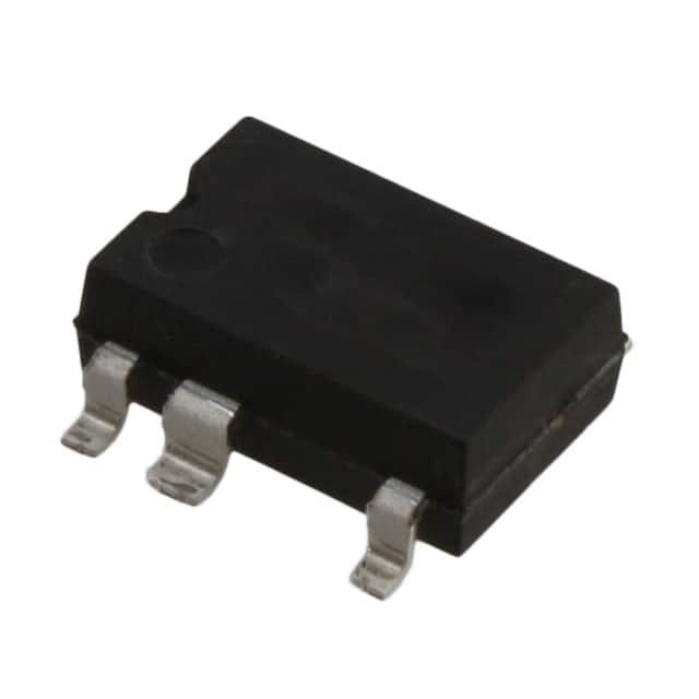
LNK304GN-TL Power Integrations
-
LNK304DG-TL Power Integrations
-
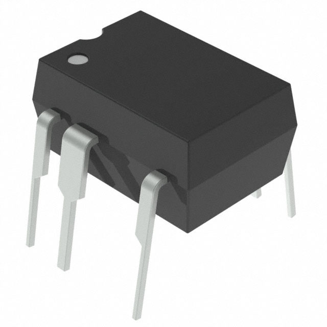
TNY277PN Power Integrations
-
TNY276PN Power Integrations
-
TNY278PN Power Integrations
-
TNY278GN-TL Power Integrations
-
TNY280GN-TL Power Integrations
-
TOP266KG-TL Power Integrations
-
TOP258PN Power Integrations
-
TOP253PN Power Integrations
-
TOP253PNAU Power Integrations

- 1500+ Daily average RFQ Volume

- 20,000.000 Standard Product Unit

- 1800+ Worldwide Manufacturers

- 15,000+ In-stock Warehouse