LM393 Pinout Guide — Dual Differential Comparator, DIP-8/SOP-8, Specifications & Common Mistakes
LM393 Pinout Guide — Dual Differential Comparator, DIP-8/SOP-8, Specifications & Common Mistakes | ICMASS
The LM393 is a dual independent voltage comparator in an 8-pin package. Each channel has the same 5-pin building block you already know: non-inverting input (+), inverting input (-), and a single output. The output is open-collector — it can pull low but cannot drive high without an external pull-up resistor. Forget the pull-up and your circuit works intermittently, works on the bench but not in production, or never works at all. This is the single most common LM393 support question on every electronics forum.
The LM393's defining advantage: its input common-mode range extends all the way down to 0V (ground). You can compare voltages near zero without a negative supply — something op-amps and many modern comparators can't do. The trade-off: inputs must stay at least 1.5V below VCC on the high side. Exceed that and the output state becomes unpredictable.
LM393 Pinout and Pin Functions
| Pin | Name | Type | Description |
|---|---|---|---|
| 1 | OUT1 | Output (Open-Collector) | Channel 1 output. Sinks current when IN1+ < IN1-. Requires pull-up resistor to go high. |
| 2 | IN1- | Input | Channel 1 inverting input. Compared against IN1+. |
| 3 | IN1+ | Input | Channel 1 non-inverting input. Compared against IN1-. |
| 4 | GND | Power | Ground (single supply) or negative rail (dual supply). Connect to 0V for single-supply operation. |
| 5 | IN2+ | Input | Channel 2 non-inverting input. Independent from Channel 1. |
| 6 | IN2- | Input | Channel 2 inverting input. Independent from Channel 1. |
| 7 | OUT2 | Output (Open-Collector) | Channel 2 output. Same open-collector structure as OUT1. Requires its own pull-up resistor. |
| 8 | VCC | Power | Positive supply rail. 2V to 36V for single-supply operation. Bypass with 0.1µF ceramic capacitor near the pin. |
Typical Application Circuit
Common Mistakes When Using the LM393
Mistake 1: Missing pull-up resistor (the #1 cause of "LM393 not working"). The output transistor can only sink current to ground. Without a pull-up resistor (typically 3.3kΩ to 10kΩ) from OUT to VCC, the output floats — it never reaches a valid logic HIGH. Your multimeter reads 0V at the output and you assume the comparator isn't switching. It is switching just fine; there's nothing pulling the output up.
Mistake 2: No hysteresis = oscillation at the threshold. When the input signal crosses the reference voltage slowly (any real-world sensor signal, a charging capacitor, a temperature change), noise around the threshold causes the output to chatter at hundreds of kHz. The fix: a feedback resistor (Rf) from OUT to IN1+. This creates two separate thresholds (Vth+ and Vth-) separated by a few tens of millivolts. The input must cross the full gap to trigger a state change. On StackExchange, users report that adding 10–50mV of hysteresis eliminated instability in every case.
Mistake 3: Both inputs outside the valid common-mode range. The LM393's inputs work from 0V to VCC−1.5V. If both inputs of a channel go above VCC−1.5V (or below ground), the output becomes unpredictable and usually goes low. This bites designers who divide a 5V rail with equal resistors expecting a 2.5V threshold on a 3.3V VCC — 2.5V is above 3.3−1.5=1.8V. The fix: use resistor ratios that keep at least one input below VCC−1.5V, or increase VCC.
Mistake 4: Pull-up voltage higher than the downstream logic can tolerate. The open-collector output lets you pull up to any voltage within the 36V rating — a feature, not a bug. But if you pull up to 12V and connect the output directly to a 3.3V microcontroller GPIO, you'll destroy the MCU. Pull up to the logic supply voltage that your downstream device expects. If you need level translation, the LM393 does it natively: connect the pull-up to the target voltage rail.
Mistake 5: Forgetting that each channel needs its own pull-up. OUT1 and OUT2 are independent open-collector outputs from separate comparators. They share a package and a VCC pin, but they do not share an output stage. If you add a pull-up on OUT1 and expect OUT2 to work, it won't. Pull each output separately.
Mistake 6: Resistor divider values too low. The LM393's inputs draw ~25nA of bias current. You don't need 1kΩ divider resistors to drive them. Use 100kΩ to 1MΩ resistors for reference dividers — the bias current error is negligible (25nA × 100kΩ = 2.5mV), and you save milliamps of quiescent current. On battery-powered designs, this alone can double run time.
Mistake 7: Connecting the output directly to a capacitive load. Long traces, MOSFET gates, and decoupling capacitors on the output pin slow down the rising edge (the pull-up resistor forms an RC filter). The comparator still works, but the output rise time stretches from nanoseconds to microseconds. For driving MOSFETs, add a gate driver or at minimum lower the pull-up to 1kΩ. For long PCB traces, keep the pull-up close to the LM393 pin, not the destination.
PCB Layout Tips
- Keep input traces short and away from the output. The output swings rail-to-rail in nanoseconds. Even 1pF of parasitic coupling from OUT1 to IN1+ can cause oscillation. Separate input and output traces by at least 2mm, and never route them parallel.
- Place the bypass capacitor within 5mm of the VCC pin. 0.1µF ceramic, directly from pin 8 to the ground plane. The LM393 switches in ~300ns; without a local bypass, the supply rail dips and both channels misbehave.
- Pull-up resistors close to the output pin. Minimize the trace length from OUT to Rpull. The high-impedance node between the open-collector transistor and the pull-up is sensitive to capacitive loading.
- Star ground for single-supply designs. Connect the LM393's GND (pin 4), the reference divider ground, the input signal ground, and the bypass cap ground at a single point. This prevents output switching currents from modulating the reference voltage through shared ground impedance.
Frequently Asked Questions
Q1: Why is my LM393 output always LOW?
A: Three likely causes, in order of probability: (1) Missing pull-up resistor on the output. The LM393 is open-collector — it cannot drive high by itself. Add 3.3kΩ to 10kΩ from OUT to VCC. (2) Both inputs are outside the valid common-mode range (0V to VCC−1.5V). Keep at least one input within range. (3) The inverting input really is higher than the non-inverting input, and the output is correctly LOW. Check your input voltages with a multimeter before blaming the IC.
Q2: How do I add hysteresis to the LM393?
A: Add a resistor (Rf) from the output to the non-inverting input. This creates positive feedback. The two thresholds become: Vth+ = VREF + (VCC − VREF) × R1/(R1+Rf) and Vth- = VREF − VREF × R1/(R1+Rf), where R1 is the resistor from VIN to IN+. For a 5V supply with VREF=2.5V, R1=100kΩ, Rf=1MΩ: hysteresis window is about 25mV. Increase Rf for less hysteresis, decrease for more.
Q3: Can I power the LM393 from a single 3.3V rail?
A: Yes, but watch the input range. Single supply works from 2V to 36V. At 3.3V VCC, the valid input common-mode range is 0V to ~1.8V (VCC−1.5V). If your reference voltage is 2.5V from a bandgap reference, it will be out of range. Either increase VCC to 5V, or use resistive dividers to keep inputs below 1.8V.
Q4: What is the difference between LM393 and LM339?
A: LM393 = dual (2 comparators in 8-pin). LM339 = quad (4 comparators in 14-pin). Same silicon, same specs, same behavior. Use LM393 when you need 1–2 comparators, LM339 when you need 3–4. Pinout is different (14-pin vs 8-pin), but the building block inside each channel is identical.
Q5: Can I use an LM393 as an op-amp?
A: No — and don't try. The LM393 is a comparator, not an op-amp. It has no internal frequency compensation, its output stage is open-collector (not push-pull), and it's optimized for saturation, not linear operation. In a closed-loop op-amp configuration, it will oscillate violently. Use an actual op-amp like LM358 for amplification. Use the LM393 for comparing two voltages and giving a digital HIGH/LOW answer.
Q6: How fast can the LM393 switch?
A: Large-signal response: ~300ns. Small-signal: ~1.3µs. Large-signal means the input overdrives the threshold by 100mV or more — the output slews at its maximum rate. Small-signal means the input is within a few mV of the threshold — the output transistor comes out of saturation slowly. For clean switching with noisy sensor signals, drive the input at least 50–100mV past the threshold.
Q7: Can the LM393 outputs be connected together (wired-OR)?
A: Yes — this is a feature of the open-collector output. Tie both OUT1 and OUT2 together with a single pull-up resistor. If either comparator pulls low, the common output goes low. Both must be off for the output to go high. This works because open-collector outputs can share a pull-up without fighting each other. Push-pull outputs would short-circuit if you tried this.
Q8: What is the maximum voltage I can pull the output up to?
A: Up to 36V, regardless of VCC. You can run the LM393 at VCC=5V and pull the output up to 24V. The open-collector transistor is rated for 36V VCEO. This is how the LM393 does level translation without extra components: power the IC from your logic rail, pull the output up to whatever voltage the next stage needs.
Related Products
Related information




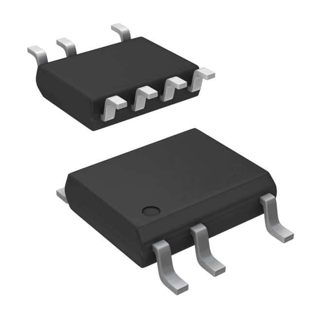
-
LNK304DN-TL Power Integrations
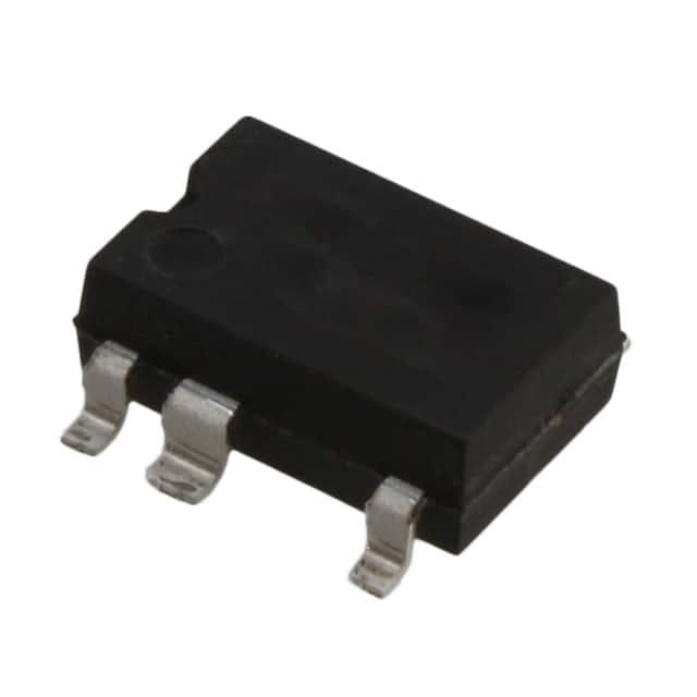
-
LNK304GN-TL Power Integrations
-
LNK304DG-TL Power Integrations
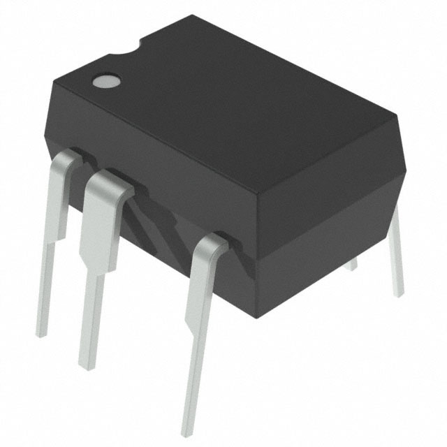
-
TNY277PN Power Integrations
-
TNY276PN Power Integrations
-
TNY278PN Power Integrations
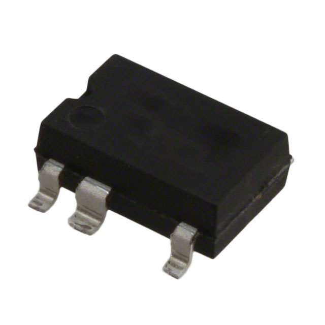
-
TNY278GN-TL Power Integrations
-
TNY280GN-TL Power Integrations
-
TOP266KG-TL Power Integrations
-
TOP258PN Power Integrations
-
TOP253PN Power Integrations
-
TOP253PNAU Power Integrations

- 1500+ Daily average RFQ Volume

- 20,000.000 Standard Product Unit

- 1800+ Worldwide Manufacturers

- 15,000+ In-stock Warehouse