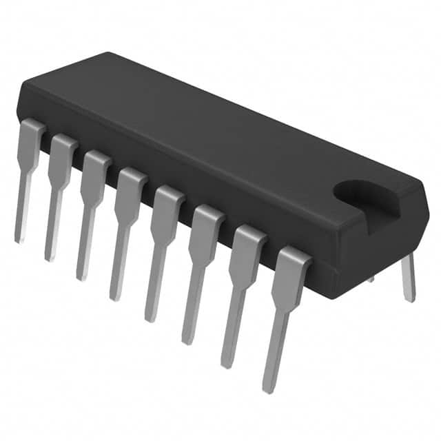
STMicroelectronics ULN2003A

- Part No.:
- ULN2003A
- Manufacturer:
- STMicroelectronics
- Package:
- 16-DIP (0.300", 7.62mm)
- Datasheet:
-
 ULN2003A.pdf
- Description:
- IC PWR RELAY 7NPN 1:1 16DIP
- Quantity:
-
Unit Price:$0
Ext Price:$0
- Payment:
-

- Shipping:
-


ULN2003A Information
- Specifications
- Product Details
- Comparison
- Tags
- Product attributes
- Attribute value
- Manufacturer:
- STMicroelectronics
- Package/Case:
- 16-DIP (0.300", 7.62mm)
- Series:
- ULx200xA
- Packaging:
- Tube
- Product Status:
- Active
- Switch Type:
- Relay, Solenoid Driver
- Number of Outputs:
- 7
- Ratio - Input:Output:
- 1:1
- Output Configuration:
- Low Side
- Output Type:
- Darlington
- Interface:
- Parallel
- Voltage - Load:
- 50V (Max)
- Voltage - Supply (Vcc/Vdd):
- Not Required
- Current - Output (Max):
- 500mA
- Rds On (Typ):
- -
- Input Type:
- Inverting
- Features:
- -
- Fault Protection:
- -
- Operating Temperature:
- -40°C ~ 85°C (TA)
- Grade:
- -
- Qualification:
- -
- Mounting Type:
- Through Hole
- Supplier Device Package:
- 16-DIP
- Datasheet:
-
ULN2003A.pdf
ULN2003A - 7-Channel Darlington Transistor Array (50V, 500 mA/Ch)
The ULN2003A is a high-voltage, high-current Darlington transistor array: seven NPN Darlington pairs in a single DIP-16 or SOP-16 package, each with a built-in 2.7 kΩ input base resistor and a common flyback diode rail on pin 9 (COM). It takes a TTL or 5V CMOS logic signal on the input side and switches up to 50V / 500 mA per channel on the output side - no external base resistors, no discrete flyback diodes, no pull-ups needed.
It's the standard answer when you need to drive relays, solenoids, stepper motors, or LED arrays from a microcontroller. Every Arduino starter kit includes one. Every 28BYJ-48 stepper motor tutorial uses one. And every engineer who's designed a relay board has probably burned one at some point. The ULN2003A is bulletproof when used correctly - but it has sharp edges that the datasheet doesn't always make obvious.
The original design dates back to Sprague (later Allegro, then TI and STMicroelectronics). The A suffix means the input series base resistor is 2.7 kΩ - this is the version you want for 5V logic. There's also the ULN2003LV for 3.3V systems, and the TPL7407LA if you need NMOS efficiency instead of Darlington heat. But for 5V relay and motor drive, the ULN2003A is still the default choice.
What Is the ULN2003A and How Does It Work?
Each of the seven channels is an NPN Darlington pair - two transistors cascaded for extremely high current gain (hFE ≥ 1000). A logic HIGH on the input pin drives ~1 mA into the Darlington base (through the internal 2.7 kΩ resistor), which turns on the output transistor pair. The output pulls to GND - it's an open-collector configuration. Your load connects between the positive supply rail and the ULN2003A output pin. Current flows from the supply, through the load, through the Darlington pair, to GND.
The COM pin (pin 9) is the common anode of seven internal clamping diodes - each diode's cathode connects to one output pin, and all anodes tie to COM. Connect COM to your inductive load's supply voltage (e.g., +12V for 12V relays), and when the Darlington turns off, the flyback current from the relay coil has a path through the internal diode back to the supply rail. No external diodes needed - in theory.
Position in the product line: The ULN2003A is the 5V-logic, 7-channel, 500 mA/ch standard. The ULN2001A is the same chip without the input base resistor (you provide your own). The ULN2004A has a higher input resistor for 6–15V logic. The ULN2803A is the 8-channel version in an 18-pin package. For 3.3V MCU designs, use the ULN2003LV - same pinout, lower input threshold.
What Are the Specifications of ULN2003A?
| Parameter | Value | Notes |
|---|---|---|
| Channels | 7 | Independent, common emitter (GND) |
| Output Voltage (VCE max) | 50V | Per channel |
| Continuous Collector Current | 500 mA per channel | Peak 600 mA |
| Total Emitter Current | 2.5A max | GND pin limit - sum of all channels |
| Input Voltage (max) | 30V | Absolute maximum on input pins |
| Input ON Voltage | 2.4V max @ IC=200mA | 3.0V max @ IC=300mA |
| Input Current | 0.93 mA typ @ VI=3.85V | ~1.35 mA max |
| VCE(sat) | 0.9V typ @ IC=100mA | 1.3V max @ IC=200mA; 1.6V max @ IC=350mA |
| DC Current Gain (hFE) | ≥ 1000 | At IC=350mA, VCE=2V |
| Clamp Diode Forward Voltage | 1.7V typ, 2.0V max | At IF=350mA |
| Turn-On Delay | 0.25 μs typ, 1.0 μs max | - |
| Turn-Off Delay | 0.25 μs typ, 1.0 μs max | - |
| Input Capacitance | 15 pF typ, 25 pF max | At 1 MHz |
| Power Dissipation (DIP-16) | 2.25W max | At TA=25°C; derate above |
| Operating Temperature | -40°C to +85°C | - |
| Package | DIP-16, SOP-16 (SOIC-16) | 2.54 mm pitch (DIP) |
Key Numbers That Matter
- Total emitter current = 2.5A max: This is the GND pin limit, and it's the real constraint in multi-channel designs. With seven channels on simultaneously, the per-channel limit drops well below 500 mA. Per the TI datasheet (SLRS027), the thermal derating curves show that with all 7 channels at 100% duty cycle and TA = 70°C, you're realistically limited to ~150 mA per channel. If you need 500 mA on all channels simultaneously, you need multiple ULN2003As or a different solution entirely.
- VCE(sat) rises with current: At 100 mA, VCE(sat) is 0.9V. At 350 mA, it's 1.6V. That means if you're driving a 12V relay that draws 200 mA with a 5V supply system, the relay actually sees about 10.3V (12V - 1.3V VCE(sat) - some wiring drop). For most relays this is fine. For motors at low supply voltages (5V stepper motors), losing 1.3V across the driver is a 26% torque loss. From our experience, this is the #1 reason 5V stepper motors feel weak with a ULN2003A - it's not the motor, it's the driver saturation voltage eating your headroom.
- VI(on) rises with total emitter current: As more channels turn on and total GND current increases, the effective emitter voltage rises (ground bounce inside the IC). This increases the input voltage needed to turn on each channel. At low total current, 2.4V might be enough. At 1A total, you could need 2.8–3.0V. For a 3.3V MCU driving all 7 channels, you're right on the edge. From our experience, if your circuit works at 5V but is flaky at 3.3V with multiple channels active, this ground-bounce effect is the culprit. Switch to the ULN2003LV or add external pull-up resistors.
- COM pin trap with stepper motors: This is the most subtle and destructive failure mode with the ULN2003A. With a 5-wire unipolar stepper motor (like the 28BYJ-48), each winding is center-tapped. When one half of a winding is pulled to GND by the ULN2003A, transformer action tries to drive the other half to 2× VSUPPLY. If COM (pin 9) is connected directly to VSUPPLY, the internal flyback diode from that undriven output to COM forward-biases, effectively shorting the winding through the diode. The result: excessive current, hot motors, burned ULN2003A channels. The fix: either leave COM floating (the diodes aren't needed for steppers since current commutates between windings), or connect COM through a Zener to V+ so it can float up to 2× VSUPPLY before the diode conducts. This is documented nowhere in the datasheet and has been discovered the hard way by generations of engineers.
What Is the ULN2003A Used For?
Relay and Solenoid Drivers
The classic application. Connect the ULN2003A input to your MCU GPIO, output to one side of the relay coil, other side of the coil to the relay supply voltage, COM to that same supply. One chip drives up to seven relays. The internal flyback diodes handle the inductive kick - but from our experience, if your relays are more than ~10 cm from the ULN2003A on the PCB, add an external 1N4148 directly across each relay coil. Long traces increase the loop inductance and the internal diodes may not clamp fast enough.
Stepper Motor Drivers (28BYJ-48 and Similar)
The ULN2003A + 28BYJ-48 unipolar stepper motor is the Arduino ecosystem's default entry point into motion control. Four channels drive the four winding ends, the two center taps connect to the motor supply voltage. The sequencing is done in software - just toggle the right pins in the right order. It's not the most efficient driver (the Darlington VCE(sat) burns power), but it's dead simple and costs almost nothing. For battery-powered stepper projects, consider a MOSFET driver instead.
LED and Lamp Drivers
Seven channels, 500 mA each, 50V tolerance - you can drive high-power LED strings, incandescent indicator lamps, or large 7-segment displays directly. The open-collector output means the LED supply voltage can be completely different from the logic voltage. 5V logic driving 24V LED strips? No problem.
Logic Buffer / Level Shifter
When you need to drive a 12V or 24V load from a 5V logic signal, the ULN2003A is a one-chip solution. No external resistors, no level-shifter ICs, no discrete transistors. From our experience, this is particularly useful in industrial control panels where you're interfacing 5V microcontroller boards with 24V PLC I/O.
Thermal Printer Head Drivers
One of the ULN2003A's original applications. The fast switching (0.25 μs) and high current make it suitable for multiplexed thermal print heads where each channel drives a heating element.
ULN2003A vs ULN2003LV vs TPL7407LA: Which Driver to Use
| Parameter | ULN2003A | ULN2003LV | TPL7407LA |
|---|---|---|---|
| Output Type | NPN Darlington | NPN Darlington | NMOS (low-side) |
| Channels | 7 | 7 | 7 |
| Max Output Voltage | 50V | 16V | 30V |
| Max Current/Ch | 500 mA | 500 mA | 500 mA |
| RDS(on) / VCE(sat) | 0.9–1.6V | 0.9–1.6V | ~0.25 Ω (<0.15V drop at 500 mA) |
| Input Threshold | ~2.4V (5V TTL) | ~1.8V (3.3V/1.8V) | ~2.5V |
| Flyback Diodes | Yes | Yes | Yes |
| Pinout | Standard DIP-16 | Standard DIP-16 | Different (TSSOP/SOIC) |
| Package | DIP-16, SOP-16 | DIP-16, SOP-16 | TSSOP-16, SOIC-16 |
| Typical Use | 5V relay/stepper | 3.3V MCU systems | Efficiency-critical, battery |
Pick the ULN2003A when you're driving relays or steppers from 5V logic and can tolerate the Darlington saturation voltage.
Pick the ULN2003LV when your MCU runs at 3.3V (ESP32, STM32, Raspberry Pi Pico) and your load voltage is 16V or below. Same pinout, drop-in replacement for 3.3V systems.
Pick the TPL7407LA when you need efficiency. The NMOS output has RDS(on) ~0.25 Ω - at 500 mA that's just 125 mV of drop (vs 1.3V for the ULN2003A), meaning far less heat. For battery-powered designs or when driving multiple channels at high current, the TPL7407LA pays for itself in saved heatsinking.
Frequently Asked Questions About ULN2003A
Q1: What is the ULN2003A used for?
A: It's primarily used to drive inductive loads (relays, solenoids, stepper motors) from microcontroller GPIO pins. It's also commonly used for LED arrays, lamp drivers, level shifting from 5V logic to higher-voltage loads, and thermal printer heads. One chip replaces seven discrete Darlington transistors plus flyback diodes plus base resistors.
Q2: Do I need to connect the COM pin (pin 9)?
A: For relays and solenoids, yes - connect COM to the same supply rail as your inductive loads. This provides the flyback current path for the internal clamp diodes. For stepper motors, you can often leave COM floating - the current commutates between windings rather than being abruptly interrupted, so the flyback diodes aren't needed. In fact, connecting COM to V+ with center-tapped unipolar steppers can cause the internal diodes to short the windings and overheat both motor and driver.
Q3: Can I use ULN2003A with a 3.3V microcontroller like ESP32?
A: It can work, but it's marginal. The ULN2003A input threshold is designed for 5V TTL - at 3.3V, you're near the minimum ON voltage of ~2.4V. With multiple channels active, ground bounce raises the effective threshold and 3.3V may no longer be enough. From our experience: if you must use a ULN2003A at 3.3V, use external pull-up resistors (4.7 kΩ to 5V) on the input pins to boost the drive voltage. Better: use a ULN2003LV, which is designed specifically for 3.3V and 1.8V logic.
Q4: Why is my stepper motor getting hot even when it's not moving?
A: If you're using a UNL2003A with a 5-wire unipolar stepper (like the 28BYJ-48) and COM is connected to V+, the internal flyback diodes are likely shorting the windings through transformer action - one half of a winding pulls the other half to 2× V+, forward-biasing the diode. Disconnect COM (leave pin 9 floating) and see if the problem goes away. If it does, that was the issue. Also check that your code isn't holding a coil energized when the motor should be idle.
Q5: Why does my ESP32/ESP8266 fail to boot when connected to a ULN2003A?
A: The ULN2003A inputs have relatively low impedance (~10–15 kΩ to GND through the internal base resistor and Darlington base-emitter junctions). During ESP boot, GPIOs 0, 2, and 15 are sampled to determine boot mode. If any of these pins are connected to ULN2003A inputs, the weak pull-down through the ULN2003A can pull them LOW, forcing the ESP into an incorrect boot mode. The fix: move ULN2003A inputs to GPIOs other than 0, 2, and 15, or add stronger external pull-up resistors (1–4.7 kΩ) on the affected boot pins.
Q6: Can I parallel ULN2003A outputs for higher current?
A: Yes. Paralleling two channels gives you ~1A capability. But the VCE(sat) doesn't halve - each Darlington still has its own saturation voltage, so current sharing isn't perfect. The internal 2.7 kΩ base resistors help by ensuring roughly equal base drive. For best results, parallel channels on the same die (adjacent pins) and stay well within the total GND pin limit of 2.5A. For 1A+ continuous applications, consider a discrete MOSFET instead.
Q7: Why are my relays chattering or ghost-triggering?
A: ULN2003A inputs should never be left floating. During MCU reset or power-up, GPIO pins may be in a high-impedance state, and a floating ULN2003A input can pick up noise and partially turn on the Darlington. Add 10 kΩ pull-down resistors from each input pin to GND. This ensures all outputs are firmly off when the MCU isn't actively driving them. Also check for crosstalk on the PCB - high-current switching traces running parallel to input traces can capacitively couple into adjacent channels.
Q8: What's the difference between ULN2003A and ULN2803A?
A: The ULN2803A is the 8-channel version in an 18-pin package. Otherwise identical: same Darlington design, same 500 mA/ch, same internal base resistors and flyback diodes. Use the ULN2003A when you need up to 7 channels; use the ULN2803A when you need 8. They're functionally interchangeable with one extra channel on the 2803.
Pricing & Availability
| Parameter | Details |
|---|---|
| Part Number | ULN2003A (TI / STMicroelectronics / Multi-source) |
| Package Options | DIP-16 (through-hole), SOP-16 (surface mount) |
| Equivalents | ULN2003LV (3.3V optimized), ULN2803A (8-channel), TPL7407LA (NMOS) |
| Condition | New, original manufacturer |
| Lead Time | In stock, ship from Shenzhen |
Contact ICMASS for current pricing on ULN2003A and compatible alternatives (ULN2003LV, ULN2803A, TPL7407LA). We stock multiple package options with full traceability. Common companion parts: 28BYJ-48 stepper motors, 5V/12V relay modules, and 2.54 mm DIP-16 IC sockets for prototyping.
| Image |
|
| Part Number | ULN2003A |
| Manufacturer | STMicroelectronics |
| Package/Case | 16-DIP (0.300", 7.62mm) |
| Series | ULx200xA |
| Packaging | Tube |
| Product Status | Active |
| Switch Type | Relay, Solenoid Driver |
| Number of Outputs | 7 |
| Ratio - Input:Output | 1:1 |
| Output Configuration | Low Side |
| Output Type | Darlington |
| Interface | Parallel |
| Voltage - Load | 50V (Max) |
| Voltage - Supply (Vcc/Vdd) | Not Required |
| Current - Output (Max) | 500mA |
| Rds On (Typ) | - |
| Input Type | Inverting |
| Features | - |
| Fault Protection | - |
| Operating Temperature | -40°C ~ 85°C (TA) |
| Grade | - |
| Qualification | - |
| Mounting Type | Through Hole |
| Supplier Device Package | 16-DIP |
User Guide
- Purchase & Inquiry
- Package
- Shipping Information
- Customer Review
You may place an order without registering to IC-MAX.COM
We strongly suggest you sign in before purchasing as you can track your order in real time.
For your convenience, we accept multiple payment methods in USD, including PayPal, Credit Card, and wire transfer.
RFQ (Request for Quotations)
It is recommended to request for quotations to get the latest prices and inventories about the part.
Our sales will reply to your request by email within 24 hours.
1. You'll receive an order information email in your inbox. (Please remember to check the spam folder if you didn't hear from us).
2. Since inventories and prices may fluctuate to some extent, the sales manager is going to reconfirm the order and let you know if there are any updates.
-

- Step1:Prepare product
-

- Step2:Vacuum packaging
-

- Step3:Anti-static bag
-

- Step4:Individual package
-

- Step5:Packaging box
-

- Step6:Barcode shipping label
Shipping starts at $40, but some countries will exceed $40. For example (South Africa, Brazil, India, Pakistan, Israel, etc.)
The basic freight (for package ≤0.5kg or corresponding volume) depends on the time zone and country.
Currently, our products are shipped through DHL, FedEx, SF, and UPS.
Delivery TimeOnce the goods are shipped, estimated delivery time depends on the shipping methods you chose:
FedEx International, 5-7 business days.
The following are some common countries' logistic time.

- Hot Sale
- Related Categories
- Include Parts
- Popular Search
- Voltage Regulators - Linear, Low Drop Out (LDO) Regulators(66836)
- Voltage Regulators - Linear Regulator Controllers(325)
- Voltage Regulators - Linear + Switching(1473)
- Voltage Regulators - DC DC Switching Regulators(35756)
- Voltage Reference(8428)
- V/F and F/V Converters(139)
- Thermal Management(515)
- Supervisors(41287)
- Special Purpose Regulators(4820)
- RMS to DC Converters(144)
The following parts include "ULN2003A" in Silicon Labs ULN2003A.
- Part Number
- Manufacturer
- Package
- Description
- TPS22919DCKR Texas Instruments 16-DIP (0.300", 7.62mm) IC PWR RELAY 7NPN 1:1 16DIP
- MIC2091-1YM5-TR Microchip Technology 16-DIP (0.300", 7.62mm) IC PWR RELAY 7NPN 1:1 16DIP
- MIC2090-1YM5-TR Microchip Technology 16-DIP (0.300", 7.62mm) IC PWR RELAY 7NPN 1:1 16DIP
- TPS22995RZFR Texas Instruments 16-DIP (0.300", 7.62mm) IC PWR RELAY 7NPN 1:1 16DIP
- TPS22975DSGR Texas Instruments 16-DIP (0.300", 7.62mm) IC PWR RELAY 7NPN 1:1 16DIP
- SIP32510DT-T1-GE3 Vishay Siliconix 16-DIP (0.300", 7.62mm) IC PWR RELAY 7NPN 1:1 16DIP
- ULN2003D1013TR STMicroelectronics 16-DIP (0.300", 7.62mm) IC PWR RELAY 7NPN 1:1 16DIP
- MIC2005A-1YM5-TR Microchip Technology 16-DIP (0.300", 7.62mm) IC PWR RELAY 7NPN 1:1 16DIP
- MIC2005A-1YM6-TR Microchip Technology 16-DIP (0.300", 7.62mm) IC PWR RELAY 7NPN 1:1 16DIP
- TPS22916BYFPR Texas Instruments 16-DIP (0.300", 7.62mm) IC PWR RELAY 7NPN 1:1 16DIP
The following parts are popular search parts in Test and Measurement.
Inventory:6,808
Please send an inquiry. Send us your inquiry, and we will respond immediately.

- 1500+ Daily average RFQ Volume

- 20,000.000 Standard Product Unit

- 1800+ Worldwide Manufacturers

- 15,000+ In-stock Warehouse